+86 180 8679 0390
Availability: | |
---|---|
Quantity: | |
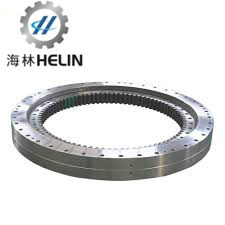
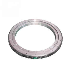
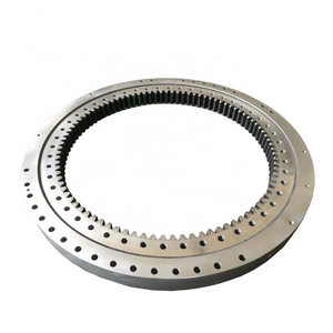
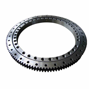
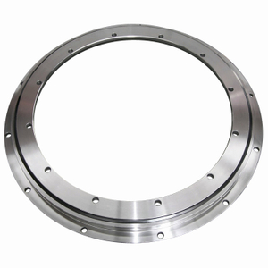
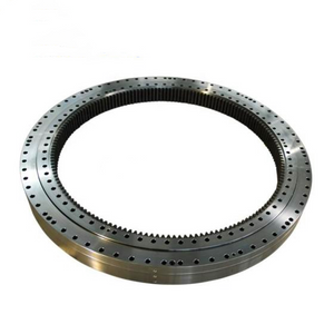
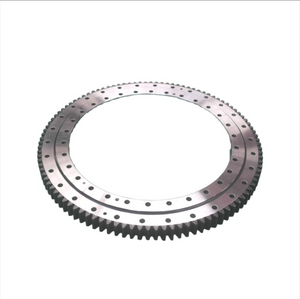
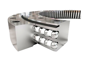
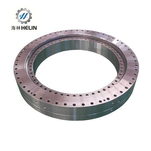
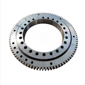
Three Row Roller Slewing Bearing(13 Series)--Internal Gear
Characteristic of structure, performance and application
The three row roller slewing bearing has three seat rings, which separate the upper, lower and radial raceways, it made each row of the roller’s load capacity can be specified and can bear different loads simultaneously. The capacity load is the largest one compare with the other three models. Due to the large size in axial and radial dimension & the solid structure, it is specially suitable for the heavy duty machinery such as wheeled excavator, wheeled crane, ship crane, ladle turrets and the heavy duty mobile crane etc.
OUR ADVANTAGE:
1. Fast: Be good at adapting, simple organization, high working efficiency, be creative and accept all kinds of customization.
2. Flexible: streamlined personnel, short communication path, and problems can be solved quickly , perfect after -sales services .
3. Efficient: employees have higher comprehensive ability, high work efficiency, high output, good quanlity and short product delivery time.
WHY CHOOSE HELIN :
1,Helin slewing bearing is located in Xuzhou, a very famous Construction Machinery Base, and has its own stable, technically sound design, development, and manufacturing team.
2. The physical factory has a strong R&D team, and production equipment is advanced, production equipment is continuously increased and updated, and there are molding batch production lines with clear division of labor and high production efficiency. (Standard models with raw material in stock , delivery time within 7 days . )
3. The slewing bearing is exported to more than 30 countries, which obtain high praise and recognition from customers all over the world .And our engineer can come to your country to do measurements .
Mob / Whatsapp / Wechat : + 86 180 8679 0390
Tel : + 86 516 8788 0390
Email : info@helin-bearing.com
tinaxzhelin@gmail.com
Kindly let us know if any inquiry ! Many thanks !
Note:
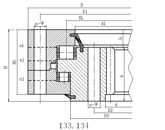
1. n1 is the nos of lubricating holes.Oil cup M10×1JB/T7940.1~JB/T7940.2.The Oil nipple's location can be change according to the user's application.
2. n-φcan change to tapped hole,the diameter of tapped hole is M,depth is 2M.
3. The tangential tooth force in the form is the max tooth force,the nominal tangential tooth force is 1/2 of the max one.
4. "K" is addendum reduction coefficient.
No. | Inxternal Gear | Dimensions | Mounting Dimension | Structural Dimension | Gear Data | Gear circumferential force | Weight | ||||||||||||||
DL | kg | ||||||||||||||||||||
mm | D | d | H | D1 | D2 | n | mm | dm | L | n1 | H1 | h | b | x | m | D e | z | Normalizing | Quenching | ||
mm | mm | mm | mm | mm | mm | mm | mm | mm | mm | mm | mm | mm | Z 104N | T 104N | |||||||
1 | 133.25.500 | 634 | 366 | 148 | 598 | 402 | 24 | 18 | M16 | 32 | 4 | 10 | 32 | 80 | 0.5 | 5 | 337 | 68 | 5 | 6.7 | 224 |
134.25.500 | 6 | 338.4 | 57 | ||||||||||||||||||
2 | 133.25.560 | 694 | 426 | 148 | 658 | 462 | 24 | 18 | M16 | 32 | 4 | 10 | 32 | 80 | 0.5 | 5 | 397 | 80 | 5 | 6.7 | 240 |
134.25.560 | 6 | 398.4 | 67 | ||||||||||||||||||
3 | 133.25.630 | 764 | 496 | 148 | 728 | 532 | 28 | 18 | M16 | 32 | 4 | 10 | 32 | 80 | 0.5 | 6 | 458.4 | 77 | 6 | 8 | 270 |
134.25.630 | 8 | 459.2 | 58 | ||||||||||||||||||
4 | 133.25.710 | 844 | 576 | 148 | 808 | 612 | 28 | 18 | M16 | 32 | 4 | 10 | 32 | 80 | 0.5 | 6 | 536.4 | 90 | 6 | 8 | 300 |
134.25.710 | 8 | 539.2 | 68 | ||||||||||||||||||
5 | 133.32.800 | 964 | 636 | 182 | 920 | 680 | 36 | 22 | M20 | 40 | 4 | 10 | 40 | 120 | 0.5 | 8 | 595.2 | 75 | 12.1 | 16.7 | 500 |
134.32.800 | 10 | 594 | 60 | ||||||||||||||||||
6 | 133.32.900 | 1064 | 736 | 182 | 1020 | 780 | 36 | 22 | M20 | 40 | 4 | 10 | 40 | 120 | 0.5 | 8 | 691.2 | 87 | 12.1 | 16.7 | 600 |
134.32.900 | 10 | 694 | 70 | ||||||||||||||||||
7 | 133.32.1000 | 1164 | 836 | 182 | 1120 | 880 | 40 | 22 | M20 | 40 | 5 | 10 | 40 | 120 | 0.5 | 10 | 784 | 79 | 15.1 | 20.9 | 680 |
134.32.1000 | 12 | 784.8 | 66 | ||||||||||||||||||
8 | 133.32.1120 | 1284 | 956 | 182 | 1240 | 1000 | 40 | 22 | M20 | 40 | 5 | 10 | 40 | 120 | 0.5 | 10 | 904 | 91 | 15.1 | 20.9 | 820 |
134.32.1120 | 12 | 904.8 | 76 | ||||||||||||||||||
9 | 133.40.1250 | 1445 | 1055 | 220 | 1393 | 1107 | 45 | 26 | M24 | 48 | 5 | 10 | 50 | 150 | 0.5 | 12 | 988.8 | 83 | 22.9 | 31.4 | 1200 |
134.40.1250 | 14 | 985.6 | 71 | ||||||||||||||||||
10 | 133.40.1400 | 1595 | 1205 | 220 | 1543 | 1257 | 45 | 26 | M24 | 48 | 5 | 10 | 50 | 150 | 0.5 | 12 | 1144.8 | 96 | 22.9 | 31.4 | 1300 |
134.40.1400 | 14 | 1139.6 | 82 | ||||||||||||||||||
11 | 133.40.1600 | 1795 | 1405 | 220 | 1743 | 1457 | 48 | 26 | M24 | 48 | 6 | 10 | 50 | 150 | 0.5 | 14 | 1335.6 | 96 | 26.3 | 36.6 | 1520 |
134.40.1600 | 16 | 1334.4 | 84 | ||||||||||||||||||
12 | 133.40.1800 | 1995 | 1605 | 220 | 1943 | 1657 | 48 | 26 | M24 | 48 | 6 | 10 | 50 | 150 | 0.5 | 14 | 1531.6 | 110 | 26.3 | 36.6 | 1750 |
134.40.1800 | 16 | 1526.4 | 96 | ||||||||||||||||||
13 | 133.45.2000 | 2221 | 1779 | 231 | 2155 | 1845 | 60 | 33 | M30 | 60 | 6 | 12 | 54 | 160 | 0.5 | 16 | 1702.4 | 107 | 32.2 | 44.5 | 2400 |
134.45.2000 | 18 | 1699.2 | 95 | ||||||||||||||||||
14 | 133.45.2240 | 2461 | 2019 | 231 | 2395 | 2085 | 60 | 33 | M30 | 60 | 6 | 12 | 54 | 160 | 0.5 | 16 | 1926.4 | 121 | 32.2 | 44.5 | 2700 |
134.45.2240 | 18 | 1933.2 | 108 | ||||||||||||||||||
15 | 133.45.2500 | 2721 | 2279 | 231 | 2655 | 2345 | 72 | 33 | M30 | 60 | 8 | 12 | 54 | 160 | 0.5 | 18 | 2185.2 | 122 | 36.2 | 50.1 | 3000 |
134.45.2500 | 20 | 2188 | 110 | ||||||||||||||||||
16 | 133.45.2800 | 3021 | 2579 | 231 | 2955 | 2645 | 72 | 33 | M30 | 60 | 8 | 12 | 54 | 160 | 0.5 | 18 | 2491.2 | 139 | 36.2 | 50.1 | 3400 |
134.45.2800 | 20 | 2488 | 125 | ||||||||||||||||||
17 | 133.50.3150 | 3432 | 2868 | 270 | 3342 | 2958 | 72 | 45 | M42 | 84 | 8 | 12 | 65 | 180 | 0.5 | 20 | 2768 | 139 | 45.2 | 62.6 | 5000 |
134.50.3150 | 22 | 2758.8 | 126 |