1. Three-row roller slewing support structure
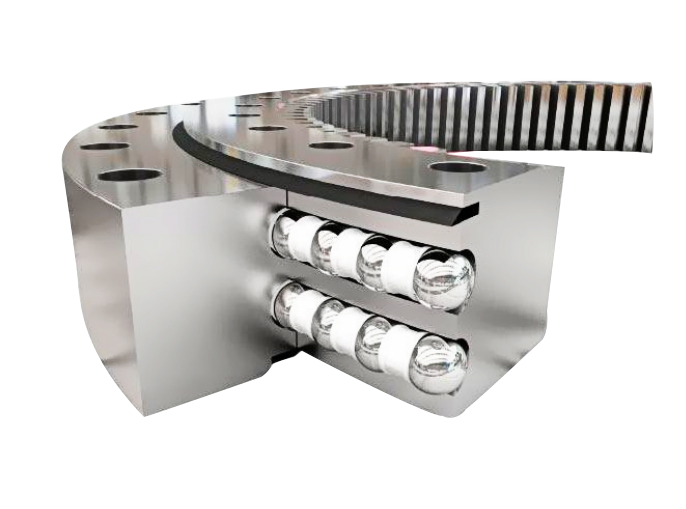
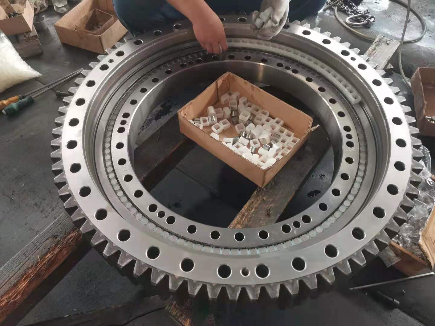
The structure o f the three-row roller slewing bearing mainly consists of three rolling rings, an upper pressure ring, a lower pressure ring, and a nose ring. The upper and lower rows of rollers are arranged horizontally, and the middle row of rollers is arranged vertically. The nose ring can be made into an inner gear ring or an outer gear ring according to the equipment structure and work needs: the upper and lower pressure rings are adjusted by the axial gap between the upper and lower pressure rings, and the gap is adjusted by the gasket, which is fixed by bolts and rotates relative to the nose ring. The axial force in the two directions and the tipping moment are borne by the upper and lower horizontal rollers, and the radial force is borne by the vertically arranged third row of rollers. Depending on the characteristics of the load, the upper and lower rows of rollers can be of the same diameter or different diameters.
The three-row roller slewing bearing is also known as the combined slewing bearing. It is a new type of support with high load-bearing capacity. It is mainly used in the occasions where the load is large, the load is more complex, and the large tilting moment is required. The axial force and tilting moment in two directions borne by the slewing ring are borne by the upper and lower rows of horizontal rollers, and the radial force is borne by the third row of rollers arranged vertically. The bearing capacity of each rolling element has a clear division of labor. The upper and lower rows of rollers bear 90°, and the bearing capacity of each bearing roller is fully utilized. Therefore, it has a large axial force, radial force and overturning moment bearing capacity, which satisfies the special requirements of construction machinery. It is the requirement of 360° slewing support for cranes, stackers, ladle turrets, etc.
2. Main features
1. Compared with cross-roller support, under the same support diameter, the number of rolling elements (contact points) is increased, thus reducing the load on each rolling element; compared with double-row ball support, the number of rolling elements After the contact is changed to line contact, the contact stress can be reduced and the bearing capacity can be improved.
2. Since the radial force and the axial force are respectively borne by the two rows of rollers, the reaction force direction is consistent with the main direction of the load received by the support, so the contact load between the rollers and the raceway can be reduced.
3. Under the condition of bearing the same load, it has smaller dimensions, smaller cross-section, and lighter weight than other types of supports, which can save materials and reduce material costs.
4. The raceway of the rolling ring is flat and cylindrical, making it easier to process.
5. In addition to bearing the radial force, the vertical rollers also have the guiding function of bearing the tipping moment.
Following is three row roller slewing bearing size information :
Note:
1. n1 is the nos of lubricating holes.Oil cup M10×1JB/T7940.1~JB/T7940.2.The Oil nipple's location can be change according to the user's application.
2. n-φcan change to tapped hole,the diameter of tapped hole is M,depth is 2M.
3. The tangential tooth force in the form is the max tooth force,the nominal tangential tooth force is 1/2 of the max one.
4. "K" is addendum reduction coefficient.
| No. | External Gear | Dimensions | Mounting Dimension | Structural Dimension | Gear Data | Gear circumferential force | Weight |
| DL | kg |
| mm | D | d | H | D1 | D2 | n | mm | dm | L | n1 | H1 | h | b | x | m | D e | z | Normalizing | Quenching |
|
| mm | mm | mm | mm | mm | mm | mm | mm | mm | mm | mm | mm | mm | Z 104N | T 104N |
|
| 1 | 131.25.500 | 634 | 366 | 148 | 598 | 402 | 24 | 18 | M16 | 32 | 4 | 10 | 32 | 80 | 0.5 | 5 | 664 | 130 | 5 | 6.7 | 224 |
| 132.25.500 | 6 | 664.8 | 108 |
| 2 | 131.25.560 | 694 | 426 | 148 | 658 | 462 | 24 | 18 | M16 | 32 | 4 | 10 | 32 | 80 | 0.5 | 5 | 724 | 142 | 5 | 6.7 | 240 |
| 132.25.560 | 6 | 724.8 | 118 |
| 3 | 131.25.630 | 764 | 496 | 148 | 728 | 532 | 28 | 18 | M16 | 32 | 4 | 10 | 32 | 80 | 0.5 | 6 | 808.8 | 132 | 6 | 8 | 270 |
| 132.25.630 | 8 | 806.4 | 98 |
| 4 | 131.25.710 | 844 | 576 | 148 | 808 | 612 | 28 | 18 | M16 | 32 | 4 | 10 | 32 | 80 | 0.5 | 6 | 886.8 | 145 | 6 | 8 | 300 |
| 132.25.710 | 8 | 886.4 | 108 |
| 5 | 131.32.800 | 964 | 636 | 182 | 920 | 680 | 36 | 22 | M20 | 40 | 4 | 10 | 40 | 120 | 0.5 | 8 | 1006.4 | 123 | 12.1 | 16.7 | 500 |
| 132.32.800 | 10 | 1008 | 98 |
| 6 | 131.32.900 | 1064 | 736 | 182 | 1020 | 780 | 36 | 22 | M20 | 40 | 4 | 10 | 40 | 120 | 0.5 | 8 | 1102.4 | 135 | 12.1 | 16.7 | 600 |
| 132.32.900 | 10 | 1108 | 108 |
| 7 | 131.32.1000 | 1164 | 836 | 182 | 1120 | 880 | 40 | 22 | M20 | 40 | 5 | 10 | 40 | 120 | 0.5 | 10 | 1218 | 119 | 15.1 | 20.9 | 680 |
| 132.32.1000 | 12 | 1221.6 | 99 |
| 8 | 131.32.1120 | 1284 | 956 | 182 | 1240 | 1000 | 40 | 22 | M20 | 40 | 5 | 10 | 40 | 120 | 0.5 | 10 | 1338 | 131 | 15.1 | 20.9 | 820 |
| 132.32.1120 | 12 | 1341.6 | 109 |
| 9 | 131.40.1250 | 1445 | 1055 | 220 | 1393 | 1107 | 45 | 26 | M24 | 48 | 5 | 10 | 50 | 150 | 0.5 | 12 | 1509.6 | 123 | 22.9 | 31.4 | 1200 |
| 132.40.1250 | 14 | 1509.2 | 105 |
| 10 | 131.40.1400 | 1595 | 1205 | 220 | 1543 | 1257 | 45 | 26 | M24 | 48 | 5 | 10 | 50 | 150 | 0.5 | 12 | 1665.6 | 136 | 22.9 | 31.4 | 1300 |
| 132.40.1400 |
|
|
|

 English


 f the three-row roller slewing bearing mainly consists of three rolling rings, an upper pressure ring, a lower pressure ring, and a nose ring. The upper and lower rows of rollers are arranged horizontally, and the middle row of rollers is arranged vertically. The nose ring can be made into an inner gear ring or an outer gear ring according to the equipment structure and work needs: the upper and lower pressure rings are adjusted by the axial gap between the upper and lower pressure rings, and the gap is adjusted by the gasket, which is fixed by bolts and rotates relative to the nose ring. The axial force in the two directions and the tipping moment are borne by the upper and lower horizontal rollers, and the radial force is borne by the vertically arranged third row of rollers. Depending on the characteristics of the load, the upper and lower rows of rollers can be of the same diameter or different diameters.
